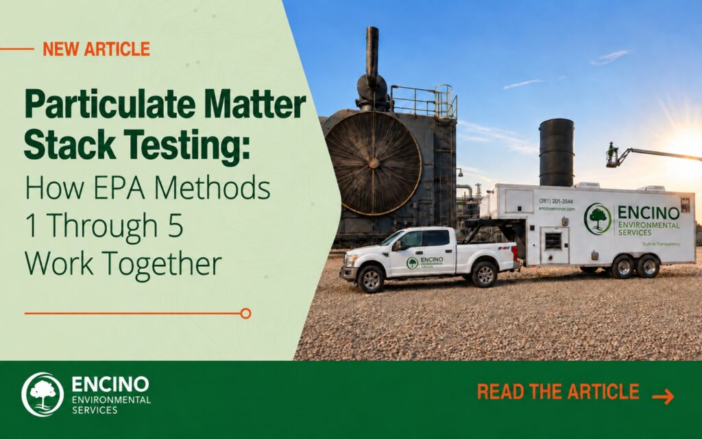
Particulate Matter Stack Testing: How EPA Methods 1 Through 5 Work Together
Particulate matter stack testing is a coordinated measurement process. Before a testing team can determine how much particulate matter is leaving a stationary source, it must identify a representative sampling location, measure the movement and composition of the exhaust gas, account for moisture and collect the sample at the correct rate.
EPA Methods 1 through 5 provide the foundation for that work. Each method answers a different technical question, and the results are combined to determine a particulate concentration or mass emission rate that can be compared with the applicable permit or regulatory limit.
Understanding how these methods work together helps environmental, facility and operations teams prepare for testing, support valid field measurements and evaluate the final report.
Key Takeaways
- Particulate matter testing relies on several measurements that describe the stack, exhaust stream and collected sample.
- EPA Methods 1 through 4 provide information needed to conduct and calculate a Method 5 particulate test.
- Isokinetic sampling helps the collected sample represent the particles moving through the stack.
- The applicable permit, regulation and approved test protocol determine the correct methods, operating conditions, test duration and reporting requirements.
- Stack design, site access, weather and process conditions influence the equipment and setup needed for the test.
- Process and control-device records provide essential context for interpreting the emissions result.
What Does Particulate Matter Stack Testing Measure?
Particulate matter, commonly abbreviated as PM, includes solid particles and liquid droplets suspended in an exhaust stream. Depending on the source and applicable requirement, particulate emissions may include dust, ash, metals, condensed material or particles generated by combustion and industrial processes.
Particulate matter stack testing directly measures PM released through a stack or duct. For a conventional EPA Method 5 test, the testing team extracts a measured volume of stack gas and collects filterable particulate matter in the front portion of the sampling train. The recovered material is analyzed gravimetrically, meaning its mass is determined by weight under controlled laboratory procedures.
The resulting mass is evaluated with the measured sample volume and stack conditions. Depending on the applicable requirement, the final result may be expressed as:
- Particulate concentration, such as grains per dry standard cubic foot
- Mass emission rate, such as pounds per hour
- Emissions per unit of production or heat input
- Control-device collection or removal efficiency
The required result and units should be confirmed during permit and method review. A permit may express a filterable particulate matter limit as a concentration, mass emission rate or production-based standard. The governing requirement determines the required test conditions, calculation basis and reporting units.
Why EPA Methods 1 Through 5 Work as a System
Method 5 provides the procedures for collecting filterable particulate matter, but the test cannot be designed, performed or calculated from the filter catch alone. Information from the supporting methods is used to establish where to sample, how fast the exhaust is moving, the characteristics of the stack gas and how much moisture it contains.
| EPA Method | What It Determines | How It Supports Particulate Testing |
|---|---|---|
| Method 1 | Sampling location and traverse points | Establishes where measurements are collected across the stack or duct to obtain a representative sample |
| Method 2 | Stack gas velocity and volumetric flow rate | Supports isokinetic sampling and the calculation of mass emissions over time |
| Method 3 | Stack gas composition and dry molecular weight | Supports gas-density, flow and method-specific calculations |
| Method 4 | Moisture content of the stack gas | Supports dry-basis corrections, sample-volume calculations and isokinetic sampling settings |
| Method 5 | Filterable particulate matter | Collects particulate material from a measured volume of stack gas for recovery, analysis and calculation |
The applicable regulation or permit may prescribe variations or additional methods. The testing team should confirm the full method set before developing the protocol or mobilizing equipment.
Method 1: Choosing a Representative Sampling Location
Exhaust conditions are not always uniform across a stack. Velocity, temperature and particle distribution can vary, particularly near bends, fans, dampers, expansions or other flow disturbances.
EPA Method 1 establishes the sampling location and the number and placement of traverse points across the stack cross-section. Instead of taking the entire sample from one convenient position, the testing team moves the probe through the required points. This approach accounts for variation across the gas stream and improves the representativeness of the measurement.
Port location and stack geometry should be reviewed early. Inadequate straight-run distances, inaccessible ports, small ducts or cyclonic flow can affect the testing approach and may require additional evaluation or agency coordination.
For a new stack that does not yet have test ports, early coordination can prevent costly modifications and testing delays. Encino can provide project-specific recommendations for test-port placement and size, along with platform access, clearance, handrail and other stack features needed to support safe and representative testing. Encino’s test-port placement guide can help facility and engineering teams address these requirements before construction is complete.
Method 2: Measuring Velocity and Flow
EPA Method 2 determines stack gas velocity and volumetric flow rate. A testing team commonly uses an S-type Pitot tube to measure velocity pressure at the traverse points established under Method 1, along with stack temperature and pressure information.
Flow data serve two important purposes during particulate testing. First, the measurements help the tester set and adjust the sampling rate at each point. Second, volumetric flow may be combined with particulate concentration to calculate the mass of PM released over time.
Changing production rates, fan operation, duct conditions and control-device settings can affect gas flow. Facility operating records collected during each run help show whether the measured conditions align with the required test scenario.
Method 3: Understanding Stack Gas Composition
EPA Method 3 determines carbon dioxide, oxygen, excess air and dry molecular weight using the procedures specified by the method.
The dry molecular weight helps establish gas density and supports velocity, flow and sampling calculations. Oxygen or carbon dioxide measurements may also be used when a regulation requires an emissions result corrected to a specified diluent level.
The test protocol should identify the required Method 3 approach and how the data will be used in the final calculations.
Method 4: Accounting for Moisture
EPA Method 4 determines the moisture content of the stack gas. Moisture affects gas volume and the relationship between wet and dry measurements. It is also used when setting and evaluating the Method 5 sampling rate.
This information allows the testing team to express results on the basis required by the applicable limit, such as dry standard conditions. Moisture can also create practical challenges during fieldwork. Sampling equipment must be operated and temperature-controlled according to the method so that condensation or freezing does not compromise sample collection.
Method 5: Collecting Filterable Particulate Matter
EPA Method 5 uses a sampling train that generally includes a nozzle, heated probe, filter assembly, moisture collection components, pump and calibrated metering system. The nozzle is inserted into the stack and moved through the required traverse points during the test run.
The sampling system draws a measured volume of exhaust gas through the nozzle and filter. Filterable particulate matter is captured on the filter and in the front portion of the sampling train. After each run, the testing team completes the required recovery procedures and preserves the samples for laboratory analysis.
The laboratory determines the recovered particulate mass. Field measurements, sample volume, laboratory results and method-specific calculations are then combined to produce the final particulate concentration or emission rate.
Where Is EPA Method 5 Testing Used?
Baghouse outlet testing is one of the most familiar applications of EPA Method 5, but particulate testing is used across a much wider range of stationary sources. Depending on the applicable permit, regulation and approved test protocol, Encino performs Method 5 testing on sources such as:
- Baghouses, including those serving asphalt plants and manufacturing operations
- Stationary engines and backup generators at data centers, natural gas facilities and other critical infrastructure
- Landfill combustion equipment, including enclosed ground flares, thermal oxidizers and gensets
- Incinerators, including those used by wastewater treatment facilities
- Crematory units
- Exhaust streams controlled by scrubbers
- Boilers, kilns and other industrial combustion sources
Some sources, particularly incinerators, may require particulate testing as one component of a larger multi-pollutant testing program. The full scope should be defined through permit and regulatory review before the test plan is developed.
What Is Isokinetic Sampling?
Particles do not always follow changing gas-flow paths as readily as gases do. Their movement is affected by particle size, density and momentum. That makes the velocity at the sampling nozzle especially important.
During isokinetic sampling, the gas enters the sampling nozzle at approximately the same velocity as the surrounding gas is moving through the stack at that point. The tester uses the Method 2 velocity information, Method 3 gas data and Method 4 moisture estimate to select the nozzle and control the sampling rate throughout the run.
If the sampling velocity differs too much from the stack gas velocity, the collected particle distribution and mass can be biased. Method 5 includes procedures and acceptance criteria for evaluating the isokinetic sampling rate.
This is one reason particulate testing requires continuous attention during a run. Stack conditions can change with production, process or control equipment, and the tester may need to adjust the sampling rate while maintaining the method requirements.
What Happens During a Particulate Matter Stack Test?
Although every test program is source-specific, the field process generally includes the following stages.
Pre-test review and setup planning
For a source Encino has not previously tested, the project team may request photographs of the test ports, stack and surrounding area. Port dimensions, platform access, available staging areas and other site information help the tester evaluate the ease of setup, identify special needs and determine which equipment and backups should be mobilized. This advance review helps the team arrive with project-specific equipment and appropriate backups.
The project requirements, stack design, access and anticipated weather and process conditions determine the most practical equipment configuration. On some projects, the sampling equipment can be positioned near the test ports. On others, the sampling train may be located on the stack or in a manlift while the meter box and operator remain on the ground. Even a repeat project may require a different setup when weather or process conditions change.
The testing team confirms stack dimensions, ports, traverse points, gas flow, temperature and estimated moisture. These measurements inform nozzle selection, sampling-train setup and run planning. The team also completes required equipment calibrations, leak checks and safety coordination.
Source operation
Facility operators bring the source and control equipment to the conditions specified by the applicable requirement or approved protocol. The facility records relevant information such as production rate, fuel or raw material use, pressure drop, temperatures, fan settings, bag-cleaning activity and other control-device parameters.
Sample collection
The tester moves the nozzle through the required traverse points while maintaining the sampling rate. Test programs commonly require multiple runs, with the duration and minimum sample volume established by the applicable regulation, permit or protocol.
Sample recovery and laboratory analysis
Following each run, the testing team recovers the filter and material from the specified portions of the sampling train. Careful labeling, recovery procedures, field records and chain of custody help preserve the integrity of the samples.
The laboratory conditions and weighs the recovered material according to the method. The testing provider then combines the analytical results with the field data and operating records.
Calculations and reporting
The final report documents the source, operating conditions, sampling location, methods, equipment, calibrations, quality-control results, sample recovery, laboratory analysis and calculations. The result is compared with the applicable limit using the units and averaging approach required by the permit or regulation.
Facility Conditions Can Shape the Test
The testing team controls the sampling system, but the facility controls the source being evaluated. Coordination between the two is essential.
Before test day, facility and testing personnel should confirm:
- The required production rate, load or other operating condition
- Fuel, feedstock, product mix or raw materials that must be used
- Expected operating range of the source and control device
- Stack ports, platform access, lifting and equipment-staging needs
- Power, lighting, weather protection and site-specific safety requirements
- Process and control-device data that must be recorded during each run
- Agency notification, observation and reporting requirements
At an asphalt plant equipped with a baghouse, the test plan may address both baghouse performance and plant production conditions. Relevant information may include differential pressure, cleaning cycles, bag-leak detection system readings, recent maintenance, production rate, aggregate characteristics, fuel, mix design, moisture and recycled asphalt content as required by the permit or protocol.
Weather also affects field logistics. Particulate sampling equipment must maintain method-specific temperatures and protect recovered moisture and samples. For projects in the Northeast, Encino generally recommends avoiding subfreezing winter testing when schedules allow. When testing must proceed with ambient temperatures below 32 degrees Fahrenheit, a client-provided heated work area may be required for sampling equipment and sample recovery. These arrangements should be confirmed during test planning, particularly when the sampling location is elevated.
From a Collected Sample to a Defensible Result
A final particulate result represents a chain of connected measurements and records. The sampling location must represent the gas stream. Velocity and flow must be measured correctly. Stack gas composition and moisture must support the calculations. The sampling train must operate within the method requirements. Sample recovery, laboratory analysis and facility operating records must be complete.
When these elements align, the report gives the facility a defensible measurement it can use to demonstrate compliance, evaluate control performance and make informed operational decisions.
Encino Environmental supports particulate matter testing across critical infrastructure and industrial operations. Our experience includes baghouses and asphalt plants; stationary engines and backup generators at data centers and natural gas facilities; landfill combustion equipment; incinerators; crematory units; scrubber-controlled sources; boilers; kilns; and manufacturing processes. Our team helps facilities define the testing scope, prepare the site, conduct field measurements and complete the required reporting based on the source, permit and operational objective.
For source-specific information, read Stack Emissions Testing for Baghouses and What Asphalt Plant Operators Need to Know About Air Emissions Compliance. Additional planning guidance is available in our Stack Emissions Testing FAQ and Top 10 Essentials for Optimal Stack Testing.
Plan Particulate Testing Around Your Source
Bring us your source information, permit requirement and testing deadline. Encino’s stack testing team can help you turn those requirements into a practical testing plan.
Sources
- US. Environmental Protection Agency, EMC Promulgated Test Methods
- US. Environmental Protection Agency, Method 1: Sample and Velocity Traverses
- US. Environmental Protection Agency, Method 2 and Stack Gas Flow Measurement
- US. Environmental Protection Agency, Method 3: Molecular Weight
- US. Environmental Protection Agency, Method 4: Moisture Content
- US. Environmental Protection Agency, Method 5: Particulate Matter